User Tools
Site Tools
This is an old revision of the document!
Table of Contents
Use Case
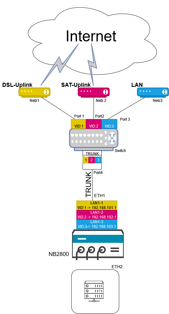
The function is mainly used to operate several WANs on one Ethernet port of the NB2800. For this purpose, a trunk is configured between the NB2800 and a managed switch, over which multiple VLANs can be transmitted. The switch assigns the VLANs to the appropriate ports and then resolves them. So the end device does not need any VLAN functions.
A use case would be an emergency car, which drives mobile missions, whose terminals have to connect to different uplinks.
VLAN Management
If you want to get access to multiple Networks with one Ethernet interface, you can use the VLAN Manager funktion. The following szenario shows an possible usecase.
 With this function you can create multiple virtual VLAN interfaces on top of one lan interface. Each of these interfaces can be assigned to a seperate network. To hold the assignment, the switch needs information, called VID, which is placed in the frame between the MAC and IP header.
Configuration Router
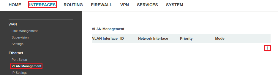
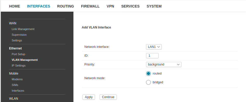
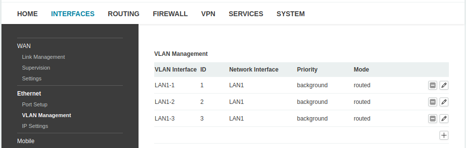
A virtual interface can be configuered in the WEB Manager at INTERFACE→VLAN MANAGEMENT→ ADD.
It is possible to set on which physical interface a subinterface is created, which VID it gets and with which priority the VLAN should be routed. The Networkmode remains routed. The prioritization classes correspond to 802.1p. To create the VLAN interface, click apply.
All Subinterfaces can be viewed in INTERFACES → VLAN Management
Configuration Switch
The Switch need to be configured to connect Ethernet Ports to the VLAN Trunk. This is ussually a Portbased to Tag-Base VLAN conversion. So that the distinction of the packages is not lost on the switch, there has to exist a Port on the Switch, which tag and untag the packages with the 802.1q(VID) header and forwards the packets to the correct Vlans. This Port has to be member in every VLAN.
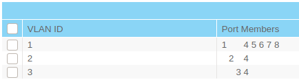
Port 1,2 and 3 belong to the respective VLAN's with ID 1,2 and 3 but do not add a VLAN Tag. Port 4 is the VLAN Trunk. It will forward the Ethernet Packets with an added VLAN Tag to the Router.
Advanced Configuration
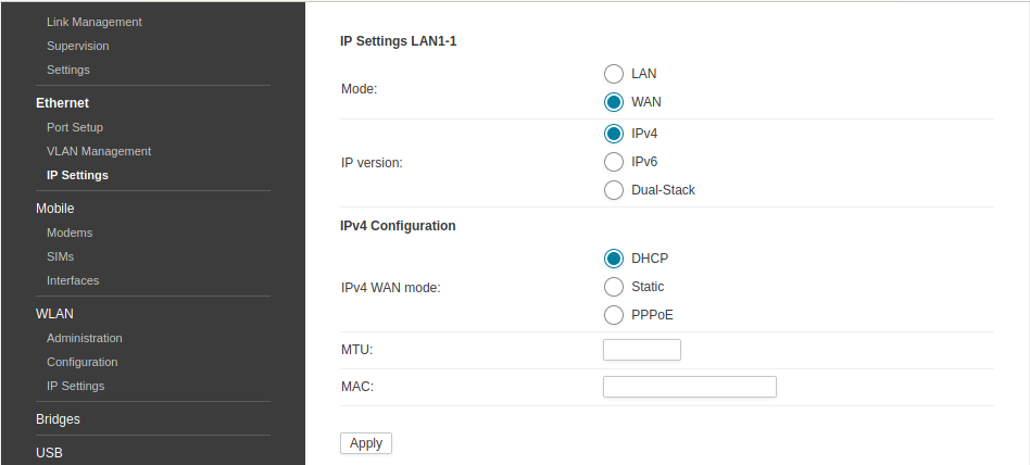
To check and improve the connection of the VLAN interfaces, by using supervision, you have to declaire each vlan as a WAN link under Interfaces → IP Settings. The IP address can be assigned statically or via DHCP. (In case of PPPoE you have to configure the access data, service name and mac adress.)
After selecting the VLANs as a WAN Link, the IP settings table will look like in the picture below.
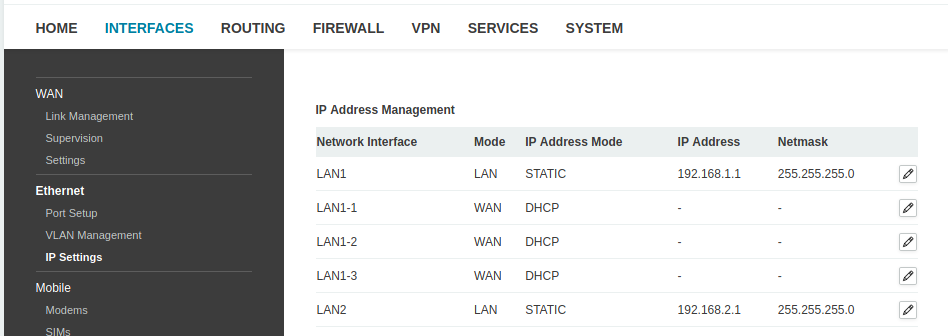
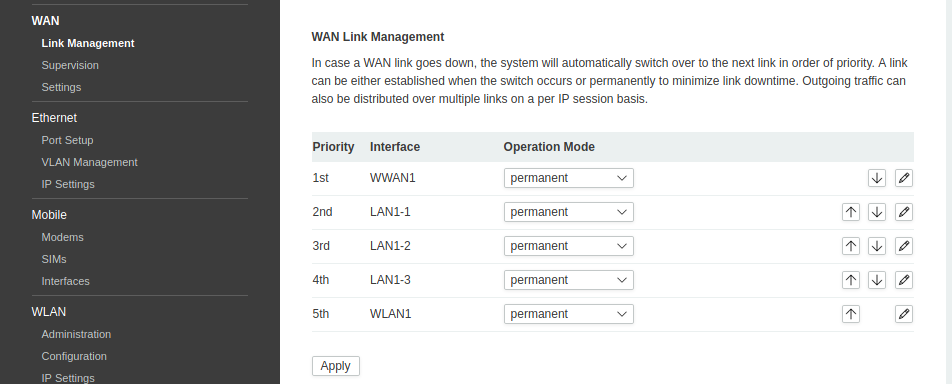
Now they will be displayed under Interfaces → Link Management.