This is an old revision of the document!
Table of Contents
NB3710 Extension Ports
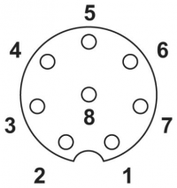
The NB3710 has an M12 extension connector with 8 pins. The 8 pins are split into two logical ports: Pins 1 to 4 represent Extension Port 1 (EP1) and pin 5 to 8 represent Extension Port 2 (EP2). In common, EP1 host the serial line of the router, which is a 3-wire RS-232.
Some NB3700 variants use the Digital I/O connector as extension connector. The same pin assignment applies for these variants.
PIN Assignment
| Pin | Port | NB3710 Base | with CAN Option | with IBIS Option | with RS485 Option | with 2nd RS-232 Option | with Audio Option |
|---|---|---|---|---|---|---|---|
| 1 | EP1 | RS-232 GND | RS-232 GND | RS-232 GND | RS-232 GND | RS-232 GND | RS-232 GND |
| 2 | EP1 | RS-232 TxD | RS-232 TxD | RS-232 TxD | RS-232 TxD | RS-232 TxD | RS-232 TxD |
| 3 | EP1 | RS-232 RxD | RS-232 RxD | RS-232 RxD | RS-232 RxD | RS-232 RxD | RS-232 TxD |
| 4 | EP1 | - | - | - | - | - | - |
| 5 | EP2 | - | GND | Call GND (Aufrufbus) | RS485 GND | 2nd RS-232 GND | |
| 6 | EP2 | - | L | Call Signal | RS485 TxD-/RxD- (A) | 2nd RS-232 TxD | |
| 7 | EP2 | - | H | Reply GND (Antwortbus) | RS485 TxD+/RxD+ (B) | 2nd RS-232 RxD | |
| 8 | EP2 | - | - | Reply Signal | - | - |
M12 Extension Connector